

Engineering Visualization
Course Code: 21EVN15/25
CIE Marks: 50
Teaching Hour/Week (L:T:P:S): 2:0:2:0
SEE Marks: 50
Total Hours of Teaching - Learning: 40
Total Marks: 100
Credits: 03
Exam Hours: 03
Course Learning Objectives:
CLO1: To understand the basic principles and conventions of engineering drawingCLO2: To use drawing as a communication mode
CLO3: To generate pictorial views using CAD software
CLO4: To understand the development of surfaces
CLO5: To visualize engineering components
Teaching-Learning (General Instructions):
Students should be made aware of powerful engineering communication tool – Drawing. Simple Case studies can be suitably selected by the teacher for hands on practice to induce the feel of fruitfulness of learning.
Appropriate Models, Power Point presentation, Charts, Videos, shall be used to enhance visualization before hands on practice.
For application problems use very generally available actual objects. (Example: For rectangular prism / object; matchbox, carton boxes, book, etc can be used. Similarly for other shapes)
Use any CAD software for generating orthographic and pictorial views.
Make use of sketch book with graph sheets for manual / preparatory sketching
Module1
Introduction: for CIE onlySignificance of Engineering drawing, BIS Conventions of Engineering Drawing, Free hand sketching of engineering drawing, Scales. Introduction to Computer-Aided Drafting software, Co-ordinate system and reference planes HP, VP, RPP & LPP of 2D/3D environment. Selection of drawing sheet size and scale. Commands and creation of Lines, coordinate points, axes, polylines, square, rectangle, polygons, splines, circles, ellipse, text, move, copy, off-set, mirror, rotate, trim, extend, break, chamfer, fillet and curves. Orthographic Projections of Points, Lines and Planes: Introduction to Orthographic projections, Orthographic projections of points in all the quadrants. Orthographic projections of lines. (Placed in First quadrant only) Orthographic projections of planes viz triangle, square, rectangle, pentagon, hexagon and circular laminae. (Placed in First quadrant only).
Application on projections of Lines & Planes (For CIE only)
Module2
Orthographic Projection of Solids: Orthographic projection of right regular solids (Solids Resting on HP only); Prisms & Pyramids (triangle, square, rectangle, pentagon, hexagon), Cylinders, Cones, Cubes, &Tetrahedron. Application problems on projection of solids. Projections of Frustum of cone, pyramid & truncated sphere (For CIE only).Module3
Isometric Projections: Isometric scale, Isometric projection of hexahedron (cube), right regular prisms, pyramids, cylinders, cones and spheres. Isometric projection of combination of two simple solids.Conversion of simple isometric drawings into orthographic views.
Problems on applications of Isometric projections of simple objects / engineering components.
Introduction to drawing views using 3D environment (For CIE only).
Module4
Development of Lateral Surfaces of Solids: Development of lateral surfaces of right regular prisms, cylinders, pyramids, and cones resting with base on HP only. Development of their frustums and truncations. Problems on applications of development of lateral surfaces like, funnels and trays.Problems on applications of development of lateral surfaces of transition pieces connecting circular duct and rectangular duct (For CIE Only)
Module5
Multidisciplinary Applications & Practice (For CIE Only): Free hand Sketching; True free hand, Guided Free hand, Roads, Buildings, Utensils, Hand tools & Furniture’s etcDrawing Simple Mechanisms; Bicycles, Tricycles, Gear trains, Ratchets, two wheeler cart & Four wheeler carts to dimensions etc Electric Wiring and lighting diagrams; Like, Automatic fire alarm, Call bell system, UPS system, Basic power distribution system using suitable software
Basic Building Drawing; Like, Architectural floor plan, basic foundation drawing, steel structures- Frames, bridges, trusses using Auto CAD or suitable software,
Electronics Engineering Drawings- Like, Simple Electronics Circuit Drawings.
Graphs & Charts: Like, Column chart, Pie chart, Line charts, Gantt charts, etc. using Microsoft Excel or any suitable software.
Course outcomes
At the end of the course the student will be able to:CO 1. Understand and visualize the objects with definite shape and dimensions
CO 2. Analyze the shape and size of objects through different views
CO 3. Develop the lateral surfaces of the object
CO 4. Create a 3D view using CAD software.
CO 5. Identify the interdisciplinary engineering components or systems through its graphical representation.
Assessment Details (both CIE and SEE)
The weightage of Continuous Internal Evaluation (CIE) is 50% and for Semester End Exam (SEE) is 50%. The minimum passing mark for the CIE is 40% of the maximum marks (20 marks) and that for SEE minimum passing mark is 35% of the maximum marks (18 marks). A student shall be deemed to have satisfied the academic requirements and earned the credits allotted to each subject/ course if the student secures not less than 35% ( 18 Marks out of 50)in the semester-end examination(SEE), and a minimum of 40% (40 marks out of 100) in the sum total of the CIE (Continuous Internal Evaluation) and SEE (Semester End Examination) taken together
Continuous Internal Evaluation (CIE)
CIE shall be evaluated for max marks 100. Marks obtained shall be accounted for CIE final marks, reducing it by 50%. CIE component should comprise of
Continuous evaluation of Drawing work of students as and when the Modules are covered on the basis of below detailed weightage.
At least one closed book Test covering all the modules on the basis of below detailed weightage.
Weightage for Test and Continuous evaluation shall be suitably decided by respective course coordinators.
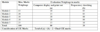
Consideration of CIE Marks
Total of (a) + (b) ÷ 2 = Final CIE marksSemester End Examination (SEE)
SEE shall be conducted and evaluated for maximum marks 100. Marks obtained shall be accounted for SEE final marks, reducing it by 50%
Question paper shall be set jointly by both Internal and External Examiner and made available for each batch as per schedule. Questions are to be set preferably from Text Books.
Evaluation shall be carried jointly by both the examiners.
Scheme of Evaluation: To be defined by the examiners jointly and the same shall be submitted to the university along with question paper.
One full question shall be set from each of the Module from Modules 1,2,3,4 as per the below tabled weightage details. However, the student may be awarded full marks, if he/she completes solution on computer display without sketch.
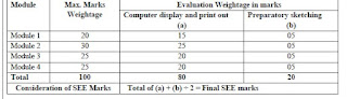
Consideration of SEE Marks
Total of (a) + (b) ÷ 2 = Final SEE marks
Suggested Learning Resources:
Text Books
Bhatt, N.D., Engineering Drawing: Plane and Solid Geometry, 53rd edition, Charotar Publishing House Pvt. Limited, 2019. K. R. Gopalakrishna, & Sudhir Gopalakrishna: Textbook Of Computer Aided Engineering Drawing, 39th Edition, Subash Stores, Bangalore, 2017 S. N. Lal: Engineering Drawing with an Introduction to AutoCAD : First-angle Projection 1st Edition, Cengage, Publication, 2018 S.N. Lal, & T Madhusudhan:, Engineering Visulisation, 1st Edition, Cengage, Publication
Luzadder Warren J., Duff John M., Fundamentals of Engineering Drawing: with an Introduction to Interactive Computer Graphics for Design and Production, Prentice-Hall of India Pvt. Ltd., New Delhi, Eastern Economy Edition, 2005.
Reference Books
Parthasarathy N. S., Vela Murali, Engineering Drawing, Oxford University Press, 2015. Dhawan R. K., A Textbook of Engineering Drawing, 3/e, S. Chand Publishing, 2019.
Venugopal K., Engineering Drawing and Graphics, New Age International publishers, 2014.
Bhattacharya S. K., Electrical Engineering Drawing, New Age International publishers, second edition 1998, reprint 2005.
Chris Schroder, Printed Circuit Board Design using AutoCAD, Newnes, 1997.
K S Sai Ram Design of steel structures, , Third Edition by Pearson
Nainan p kurian Design of foundation systems, Narosa publications
A S Pabla, Electrical power distribution, 6th edition, Tata Mcgraw hill

.png)

.png)
.png)
.png)

0 Comments